I have always wanted my own CNC router but they are really expensive to buy. After seeing some people build them online I thought it would be great to build my own. I found a great site called buildyourcnc.com by Patrick Hood-Daniel. He shows how to build a CNC router from scratch in 36 video’s on YouTube. So I decided to watch these video’s and learn how to build my own CNC. It turned out to be quite a challenge…
Linistepper version with TIP122's on the edges.
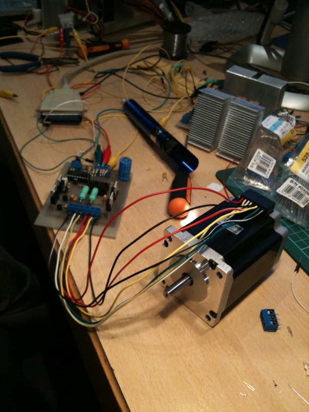
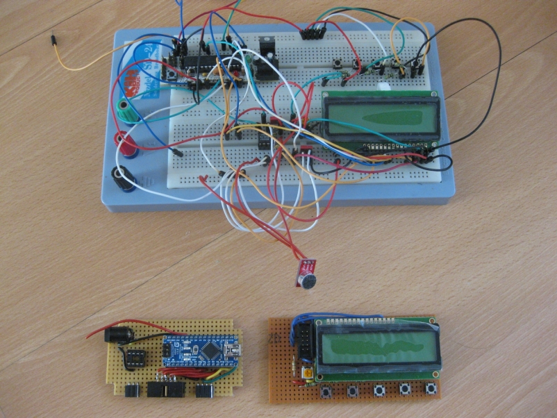
I first worked on the electronics, while doing research on stepper drivers a college/friend/fellow hacker of mine suggested to check out Linistepper V2. It’s a great open source driver based on the PIC16F628A. We decided to build the version that had the TIP122’s on the opposite edges on the board so they would be easy to mount to some old Intel CPU cooling blocks of which we had plenty in the dumpster at my work. He also etched the pcb’s for me and they turned out really nice (thanks Arnd!).

First driver assembled and running!
We also found a great set of steppers online at a great price. After all of the electronic parts were gathered we had a fun evening of soldering and pizza and pretty soon we had the first pcb assembled. You can see the heat sinks in the background.
The linistepper is a great driver that provides different stepping modes: full, half and microstepping. It supports a lot of stepper motors and provides the standard direction and step pins as input pins. Allowing it to be used on the printer port of the computer directly with software like EMC2.
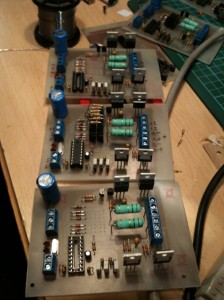
Three stepper drivers assembled.
That evening we completed all six pcb’s (three per person) and tested them all out. The only thing we ended up spending most time on was figuring out the right current limiting resistors to use for the steppers we bought.
An oops I made was to try to make the stepper driver turn the stepper by pulsing the step pin by hand but that does not provide clean step pulses of course. So after figuring that out I connected the drivers to an old printer cable and ran a test program in EMC2 to drive them.
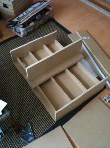
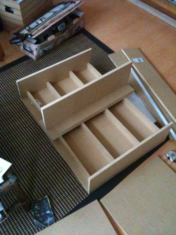
The cut MDF sheets
Next thing I did was figuring out what dimensions I wanted my CNC to be. I didn’t want to make it too small because I wanted to use it for more stuff than just pcb’s but also not too big, I should be able to carry it on my own, and of course the steppers don’t provide infinite power. So I made a sketch of the dimensions and went to a local hardware store and asked for them to cut the MDF sheets.

The 'Ikea system' for connections
I used the ‘Ikea system’ for holding the structure together, it makes for a really nice strong connection and I didn’t have to use any glue or anything. You just make a hole in the piece of wood you would like to attach and drill a hole in the connecting piece that you put a nut in and then just fasten the bold.
Buildyourcnc.com had a really nice method of creating linear bearings using skate bearings and aluminum corner sheet. It is quite easy to use but you need t make a template using another piece of aluminum with holes in it to make sure you make the four holes in exactly the right places. After that you need to make the holes threaded to be able to attach the screw that holds the bearings in place. The end result will look like this:

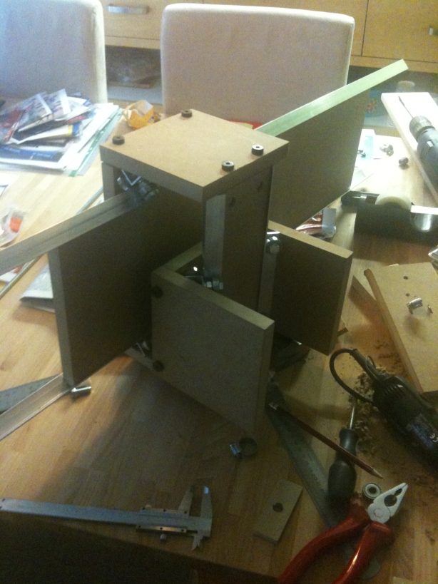
Z-gantry under construction
After this I build the Z gantry using more linear bearings and using a router to cut the edges of the MDF at a 45 degree angle at both sides so the aluminum rail would stay in place. You really don’t want to use a router in your house so I did that on my balcony 🙂
It is kind of hard to measure the with of the piece of MDF plus the two sets of rails with the bearings in between them so for the Y gantry I made a mistake and went back to the hardware store to have them cut the piece to correct size. This is not something I could do myself using a handsaw and without proper tools.
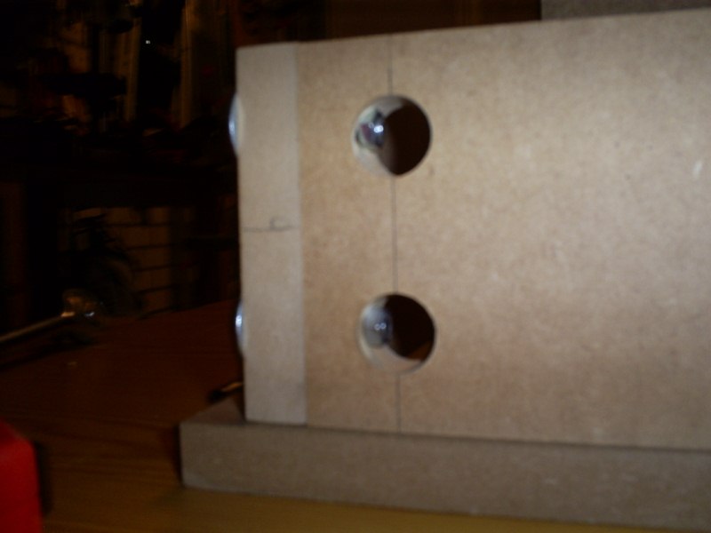
I went on to create mounts for my stepper motors and holes in the Z-gantry to support the axis. I did this by taking it apart again and drilling a hole thru both the bottom and top piece at once to make sure I did not mess up the alignment. There is no room for error.
I used a drill to carefully make a hole for a hollow worm wheel I found at the hardware store that has an M8 thread inside it. Using two of these on the same M8 thread removes any play the M8 thread has. After reassembling the Z-gantry I gave it a test run:
I was very pleased with the result and the stepper motor ran really smooth and quietly. I then build the other gantries using the same principle and tried them out, at first without the X and Y gantry steppers attached.

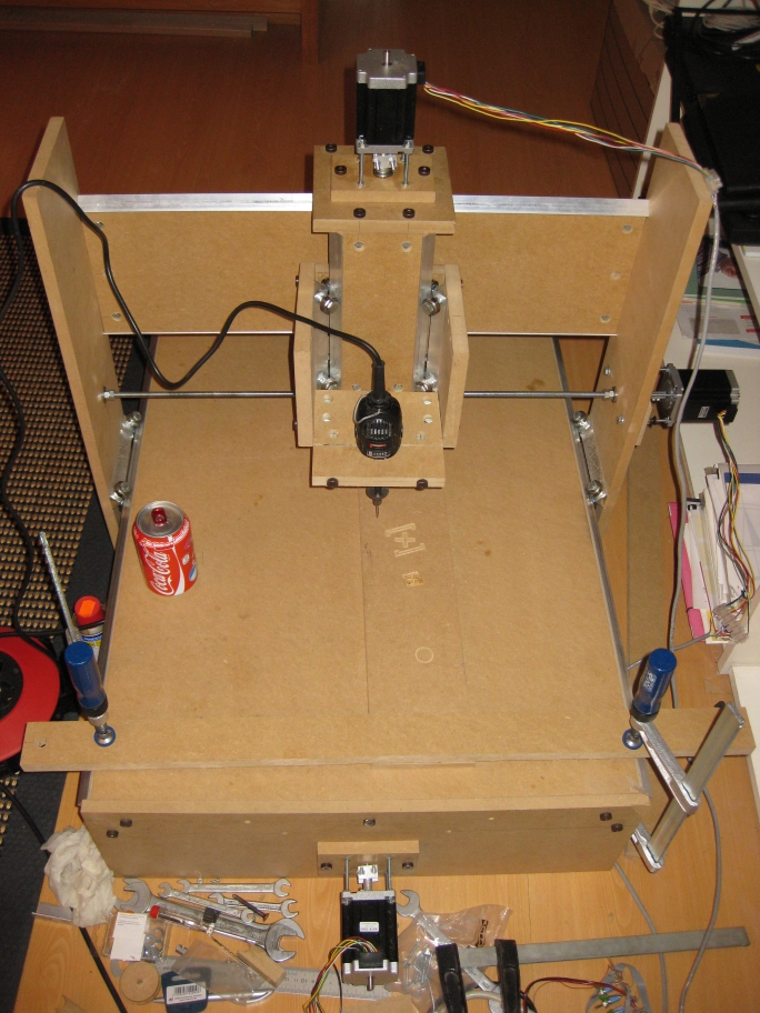
CNC router assembled. Coke can for size.
It was very nice to see it assembled for the first time and it had no play or friction. I repeated the motor steps for the other axis and added a mount for my Dremel. I first attached a pen to and made my CNC draw some stuff.

First test run.
It went ok but the stepper couplings were slipping so I found another solution that worked better and I attached my Dremel and did a first test run.
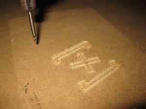
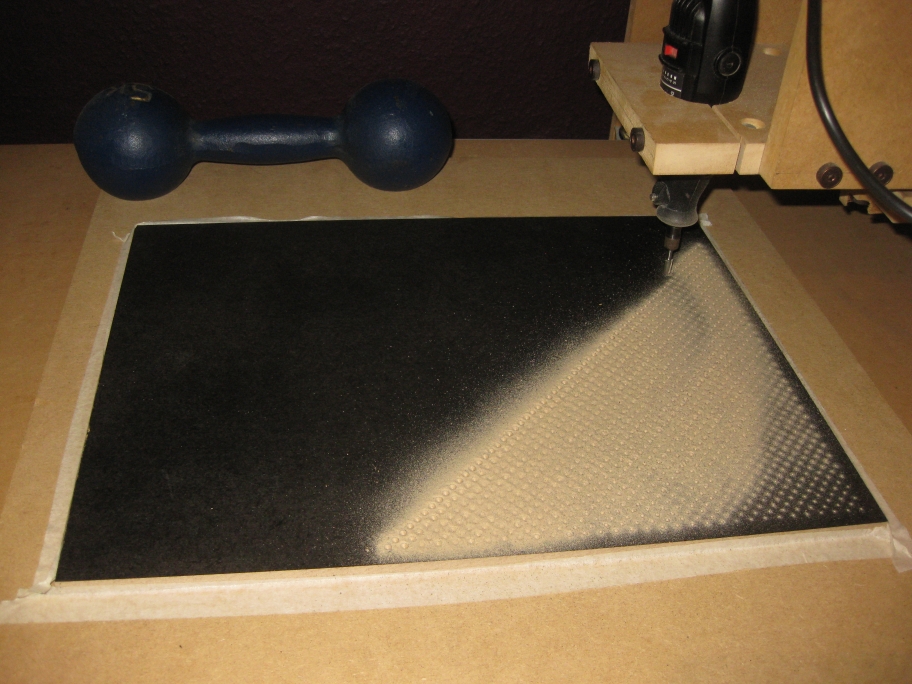
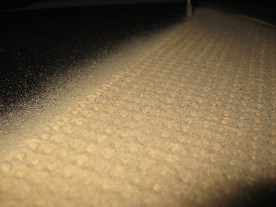
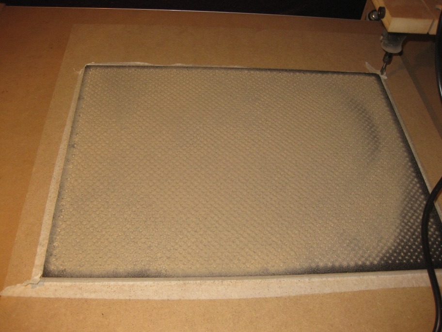
Logo test cut.
I played around a bit with the settings and made a logo and cut it. The first couple of tries did not end up well as I either cut to deep for a single pass or had the speed to high for the Dremel so it would not cut fast enough. After some tweaking I got the settings right.
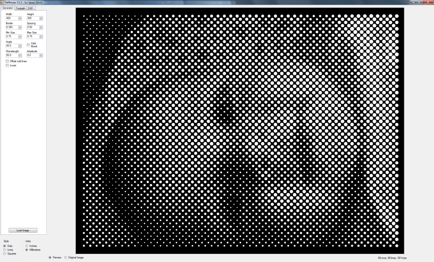
With the CNC working nicely I looked for a nice set of software that allowed me to design first and then have G-code at the end that I could let my CNC work on and EMC2 would understand. I tried alot of opensource tools to create DXF files and tried tools to convert it to G-code. Some of them worked and some of them were horrible.
Later on I found a really great plugin for Google Sketchup called Phlatscript by www.phlatforum.com. It is a really handy plugin that exports G-code directly and Sketchup lets you draw almost anything quite fast after you figure out how to use it. That however does not take long as it is very intuitive ans has a lot of online help.
I still use this workflow for my own designs. I have replaced the couplings again recently by couplings I bought on Ebay as mine kept on slipping after a while.
Using tools the proper way can be quite hard. Using simple tools to create a CNC router with no room for errors in either software, electronics or any mechanical aspect was quite a challange, but I am happy with the result.