
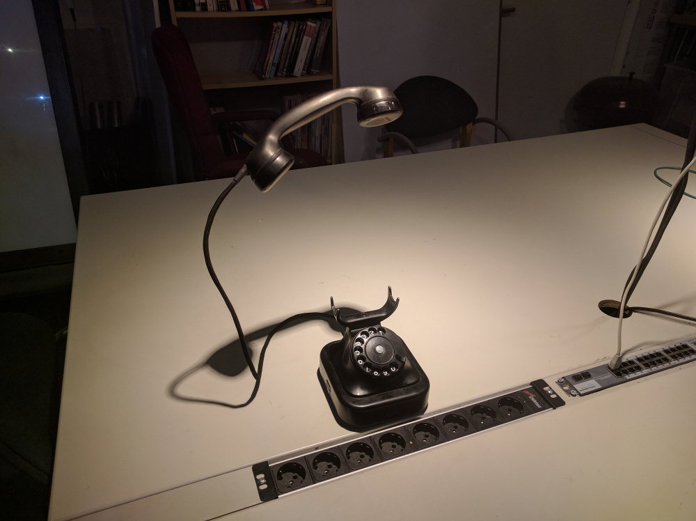
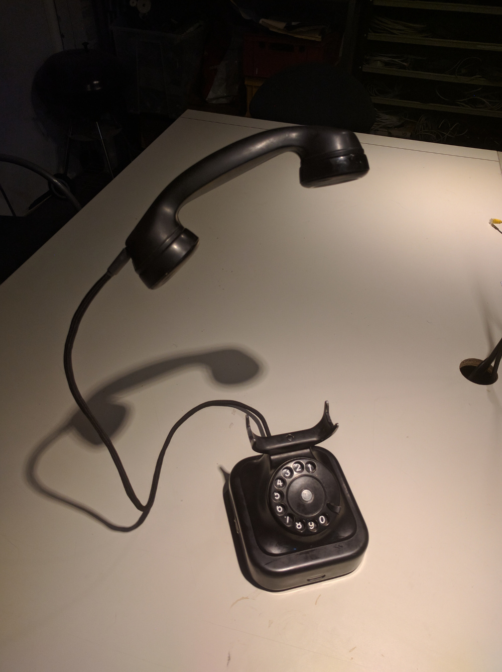
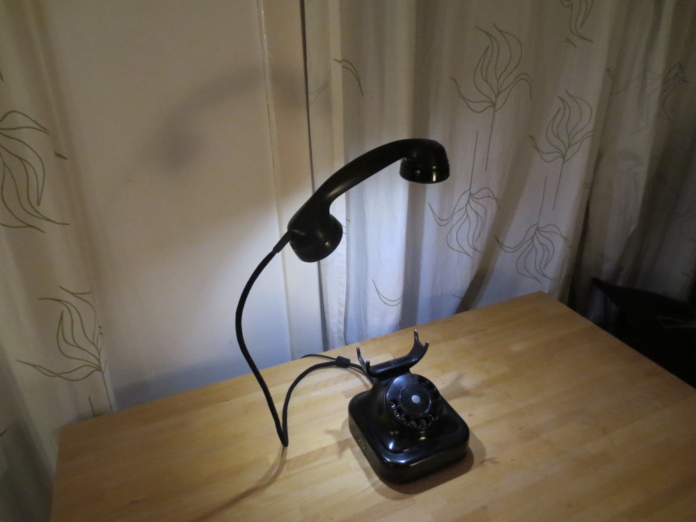
In this project I converted an old desk telephone into a lamp. It’s an old black bakelite/metal desk phone made by Heemaf type Norm 1938 made under Siemens license in The Netherlands for PTT (Dutch telecom company):
As can be seen in the video it is possible to control the phone both physically and virtual using a mobile phone for example. I was also able to make the bell ring again, I might hook it up as my next doorbell.
The build
To accomplish this I opened up the phone when I bought it and first removed all unnecessary parts, including a mechanism that turns back the phone dial upon releasing it. The process was quite interesting as I don’t take apart something that was made in 1952 every day.
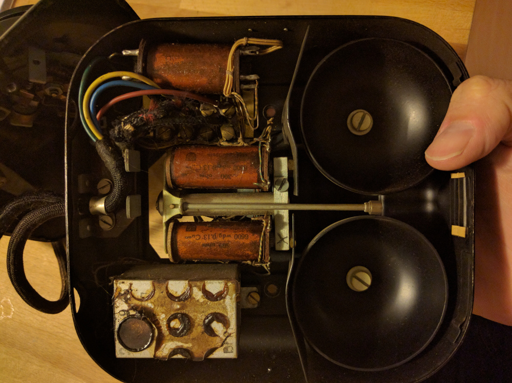
Original phone internals – bottom side
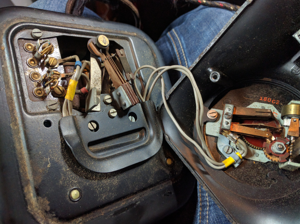
Original phone internals
I didn’t expect to get the bell working again as it is suppose to run on a 60V AC signal, but by alternating the voltage in the same frequency on one of the outputs of the H-bridge I got the desired effect (you can hear the bell at the end of the video).
Now that I wanted the bell to keep working I had another problem. The space I thought I could use by removing the bells and the coils was no longer available and I could no longer connect the potmeter and motor combo inline with the phone dail centre shaft. To resolve this I used a cross coupling so I could mount the potmeter under an angle. If the potmeter has any friction while turning the motor will slip so the potmeter will stop turning, so mounting the potmeter at exactly the right angle proved to be quite a difficult task.
Electronics
The brain of the operation is the ESP8266 WiFi SoC by Espressif Systems mounted on a NodeMCU board. It connects to a Dual H-bridge board that drives both the Potmeter motor and the coils that drive the bell. The LED’s are driven via a TIP122 darlington transistor. The power supply voltage is stepped down to around 8V using a Step down module as 12V is too much for the potmeter motor.

Schematic overview
Software
I installed the Arduino core on the ESP8266 and added the OTA Update library for easy updates to the code. The aspect of two different input methods that have to work together and keep each other in sync was quite interesting. I found out that if you read the analog input A0 too frequently the ESP8266 will actually drop it’s wifi connection as this adc is also used to monitor wifi output power internally, simply adding a delay between reads on A0 fixed this issue.
The client on mobile phone was made in html/javascript using jQuery and websockets to connect to the rotary phone. Upon rotating the dial on the rotary phone updates are send via the websocket connection to keep the mobile phone dial in sync. The values from the potmeter are mapped to degrees between 0 and 300 (physical limit of the rotary phone dial).
Photos
Parts
- Phone: Heemaf type Norm 1938
- NodeMcu
- Cross coupling
- Dual H-bridge
- Leds
- Motorized Potentiometer
- TIP122 darlington transistor
- Buck step down module
- 12V power supply
Pingback: Rotary Telephone Becomes Stylish Lamp | Hackaday
Pingback: This Week in Making: Amazing Masks, Heroic Snowflakes, and Snow Day Activities | Make:
Looks great. What type of wire did you use between the base and the handset that it is rigid like that? or how did you get it rigid like that?
Thanks! It is a 4mm brass wire. It’s actually quite stiff and strong enough to carry the horn.
Great project . What did you use and where did you purchase the flexible metal tube for the cord?
Thanks! It is a 4mm brass wire that I bought at a local hardware store. I removed the outer mesh from a ironing wire and placed it over the brass and some seperate wires (to get both the negative and positive to the LED’s.
Ooh! I made one too: http://imgur.com/gallery/Fr8yfg5
I really like the iPhone interface. I feel like that’s some next level stuff there.
For mine, I wanted to keep the original dial mechanism, so you first dial in the brightness, then an arduino counts the clicks and adjusts the brightness accordingly.
How did you get the lights to be reasonably bright? I have 3W LEDs in mine and it seems SOOOO DIM. It doesn’t put out any useful light. It’s just sculpture. Cool sculpture, but still, I’d like at least be able to read a book by it.
Hi there! Really like your build as well, I thought about keeping the original dial mechanism but wanted to also be able to turn the physical dial using a virtual dial and that is not easily possible with the original mechanism.
I am using two of the LEDs listed in my parts list, they are running on 12V. It’s not the brightest and I am not sure
if reading next to it would be a good idea. The problem is that other LEDs seem to require too much power/space/cooling to fit. If you find something else that would work I would love the know. You could ofcourse test if my LEDs are brighter then the onces you currently use.
I used these 3W warm whites from SparkFun: https://www.sparkfun.com/products/13104
I’m thinking about drilling out the holes and putting in a lens to get more light out, but I’m worried it will ruin the cool effect of the light streaming out of the little holes. Meh. Maybe I should just be happy with what I have.
Pingback: Telephone Lamp Project – Future Steve
Hey Sander, i’m working on a similar project but using these Adafruit Neopixels https://www.adafruit.com/products/2858
I’m having trouble figuring out a good way to mount these to the bottom of the handset. I’m looking at you pictures, but don’t see a clear shot at how you attached them. I worry if i try and drill out holes it will split/crack due to the little holes that are there already to pick up the users voice. Any help would be greatly appreciated.
Thank you,
Steve
Hi Steve, Those neopixels look nice. I used a drill press to carefully drill a big hole in the hearing part of the horn as the tiny holes that are originally there are just not enough for the light to shine trough imho. On my horn the hearing piece is on a thread so I could just screw it off. Actually I replaced the talking piece with a hearing piece from a different horn as the talking piece is bent and not ideal for mounting an LED behind it. Go easy and really slow as you drill, mine did not crack but I really took my time drilling it. As for mounting, both sides of the horn had screws after I removed the internals. So I attached a small piece of aluminum that I bent until I could mount the LED behind it so it was right in the center of the hole. Good luck! Would like to see your build! Oh and mine also responds to Amazon Alexa and the bells inside the phone ring when someone rings the doorbell 🙂
Hi Sander,
I love your phone – it truly is an art piece.
As I do not have the expertise in electronics to build such a lamp – would you consider building one for me under contract.
Before I ask any more questions – I will wait for your reply.
Thank you for your consideration.
Regards
Roy
Hi Roy, thanks for your kind comment!
I will contact you via email about building a phone for you.