
So what do you do if you want to fly FPV but the winter weather is really bad?
You build a micro FPV quadcopter you can fly around the house!
It is an easy build and the parts are cheap. This is what it looks like:

DIY micro FPV quad ready to fly
It consists of a 5.8 Ghz video transmitter and a small camera and an antenna. It is build on top of a standard Eachine H8 Mini Quadcopter. This setup is cheap and still flies for a couple of minutes depending on the type of battery that is connected.
Power regulation
The H8 Mini is a quadcopter with brushed motors so if you would try to connect the video transmitter (vtx) directly you would lose signal due to the power noise from the brushed motors so that needs to be filtered. The vtx runs on 3.3v and the 1S LiPo
puts out 4.2V when fully charged so that would kill the vtx.
Therefore I decided to first boost the voltage to 5V and then use a regulator to bring it back to 3.3v. This way you always provide 3.3v regardless of the exact voltage in the 1S LiPo.
Schematic
You end up with the following diagram:
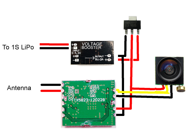
Schematic showing connections to power regulators
Update: there is a small error in the schematic above: the camera ground wire is not connected to ground but audio out, I will fix this soon. Use the labels on the pcb: the gnd wire is the one below the audio out wire.
Please note that the tab on top of the 3.3v voltage regulator (top part of the image above) is not ground (GND) but the output voltage (v-out) so make sure you isolate the whole part well.
Build
I started by connecting a power and ground wire to the H8 mini pcb. It is quite easy to solder a wire to the pads when you remove the battery, you don’t even need to take the quadcopter apart. See this picture:
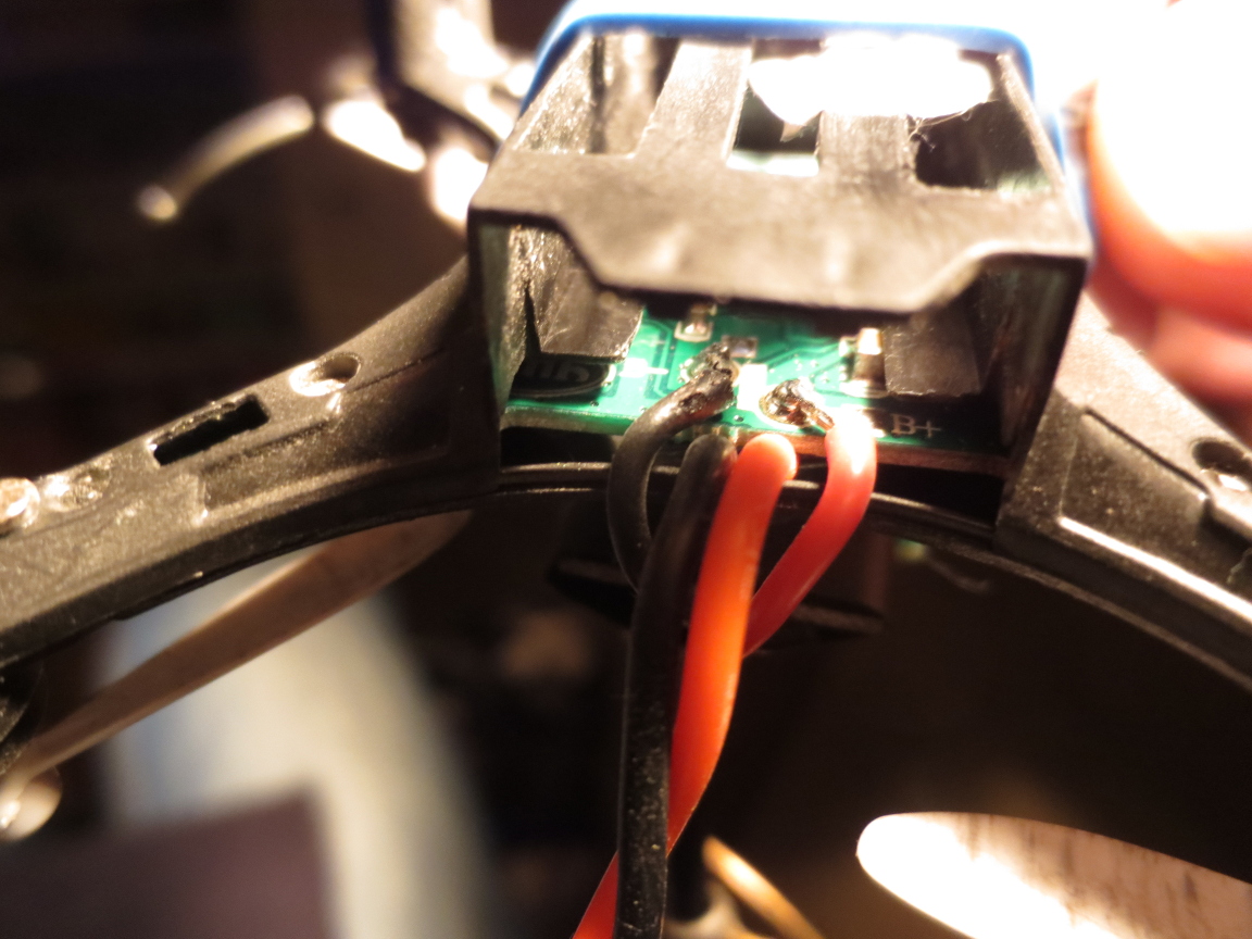
Upside down view: ground and power wire directly soldered to the h8 mini pcb
Next step is to the solder wires to the input side of the Matek board and to the output.The latter are directly connected to the input and ground pin of the AMS1117 3.3v regulator (see schematic above). next I isolated this regulator using shrink wrap and
place it on top of the Matek board. This board was also isolated with shrink wrap and hot glued to the H8 mini. I connected the boscam vtx and the camera to the output and ground wire of the 3.3v regulator. I shortened the antenna wire a bit to save weight and connected the centre wire to the antenna output of the vtx and the outer mesh to the antenna ground pins. This results in the following:
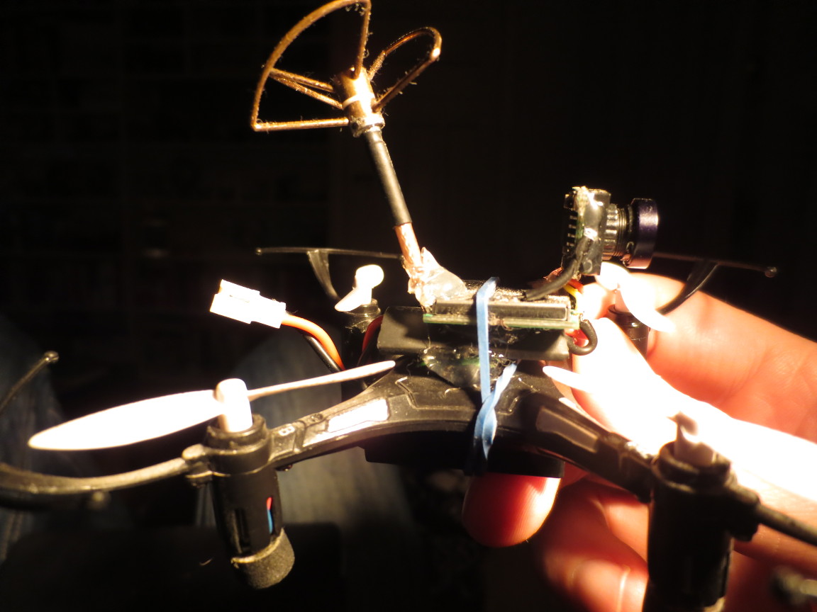
H8 mini with Matek regulator on top (3.3v regulator inside) and vtx on top of that
In the future I will try to use a wire antenna as it will be lighter and I may still get good range as the vtx is 200mw.
Parts list
- Eachine H8 Mini Headless Mode 2.4G 4CH 6 Axis RC Quadcopter RTF
- Boscam FPV 5.8G 200mW Wireless Audio Video Transmitter Module TX5823
- Matek VB2A5V DC-DC 1S Up to 5V Voltage Booster Regulation Module Converter
- FPV 5.8GHz Micro CL TX Antenna Lightweight
- 600TVL 1/4 1.8mm CMOS FPV 170 Degree Wide Angle Lens Camera
- AMS1117 3.3V regulator, search eBay
You will also need some wires and shrink wrap and hot glue.
Control (optional)
I use the FrSky Taranis 9XD Plus to control my larger quads so I found a great project online that enables you to control your mico FPV quad using this controller instead of the controller that is provided with the quad, see the nrf24-multipro project on github. You can of course also use the controller that comes with the H8 mini quad.
Hi
its very good. What is time flight?
Which is batery mAh?
It flies for about 4 mins, I use different batteries up to 300mah.
Hey Sander. Thanks for sharing this with us all. Really appreciated. Followed your instructions using the same components however mine barely takes off. It lifts off, flies for 10 seconds before slowly descending. What batteries do you use? Thanks!
Hi Alex, Strange that should not happen, the battery you get with the H8 should even let you fly for a couple of minutes.
did you try a different battery? These batteries work great for me:
http://www.hobbyking.com/hobbyking/store/uh_viewItem.asp?idProduct=24920
Good luck!
Great write-up, we need more H8 mods… this is a solid and cheap platform to work with.
Great article, I went ahead and purchased parts alrady.
Just one thing…
why would you use a step up module to get 5V first then then bring it back down to 3,3V??
I think this adds a lot of weight to the build, and it may also waste some of our precious energy in conversion.
Why not use somthing like this: https://www.pololu.com/product/2122
It will always provide you with 3,3V output, no matter if input is higher or lower.
It can provide at least 750mA output which should be more than enough.
Hi Sebastian,
Thanks for your comment, I think I will order that regulator and see if it works.
My current setup does not include any LC filter and I hope this will also not be
needed with this regulator as that would add the weight we are trying to loose 🙂
Also it might not be a good idea to wrap this is shrink wrap in the same way I
currently do as a note on that page reads:
During normal operation, this product can get hot enough to burn you.
Take care when handling this product or other components connected to it.
Hi,
i think considering LC filter there should be no change, since your setup has no LC filter with it and neither does the regulator from pololu…
About the heat issue, i think we will have to try that out. I am running a 12V step down regulator from pololu on my 250 race quad to provide 12V to my cam+VTX. That reegulator is not really getting hot, just warm, and I sealed it completly in shrink tube…
I am running 4S, so its stepping from 16,6V-14V down to 12V
I guess only a test will tell about the heat
I tried several Pololu regulators but I can’t get the motor noise out of the video signal. My setup as described has about zero motor noise in the video signal so I will stick with my first setup.
Just build the little guy. It is flying and this is so much fun!
1 thing is to check the ground cable from the camera. That should be 1 down on the transmitter. Just check your 5.8 transmitter to see where it needs to be.
Another thing is that you don’t need the clover. Just use the bottom part and strip around 1,5 cm of the ground on the top. Works like a charm over here.
Hello,
thx for publishing the parts list, it is very valuable and time saving.
You said that you finally prefered your first 5V voltage booster because the video signal on the VTX was not noisy. But, if I am right, you didn’t tell us the reference of this voltage booster board. Could you please give us this (important) reference?
Kind Regards,
Louis
Hi Louis, I am not sure what you mean by reference? The matek board outputs a fixed 5V, this voltage is not adjustable. This 5V is then passed to the AMS1117 regulator that turns it into 3.3V. Hope that answers your question.
Hi Sander, and first of all, thanks for sharing!
i will soon receive the same configuration from banggood; except for the Vtx which is http://www.banggood.com/FPV-5_8G-200mW-32CH-Wireless-Audio-Video-AV-Transmitter-Module-FX758-2-p-980317.html .
It works under 5V so no need to step it down out of the Matek regulator.
I ll let you know how it works. I m so excited!
Hi Niko, hope your setup works good, thanks for your comment! I hope the Matek regulator is enough to keep your video signal free of electronic noise from the motors.
Great guide!
First of all let me state that I got zero experience with soldering and electronics :).
I actually had a very similar setup (without the Matek board and AMS) but the vTX got REALLY hot (I later noticed that it should accept ONLY 3.3v), luckily I did not burn it.
In my searches on how to solve this problem I found your page and it really helped!
So I built the system according to the scheme above (yes, I corrected the GND) and now instead of the vTX getting hot, the Matek board gets hot.
(it’s not burning or anything, but it’s in no way “warm”, it’s getting increasingly hotter and hotter), the vTX is still getting warm but I think it’s because it’s taped to the hot Matek board.
* I do got my Matek and AMS regulator wrapped in heat-shrink.
The video runs perfect and smooth, even with full motor throttle, zero noise, so I guess no shorts in the way.
Does that make sense? Should it run so hot? Any tips?
Thanks, glad my post was able to help you. You are lucky you didn’t burn the vtx without lowering
the power to 3.3v. Maybe exposing the Matek board to the wind your props produce might reduce the
heat? Remove some of the heatshrink? Most trouble I had was getting the video image free from motor power noise but you don’t have that problem, great!
Thanks for replying!
I will try to remove some of the heatshrink and test again.
Is it safe for the board (and the cables) to heat like that?
Also, the system weighs about 11.5g here and the H8 (also tried Hubsan H107L) is really struggling to carry it, I’m afraid to burn the motors.
I already cut the antenna to 6.5cm, did not use any hot glue, the camera wires are 1-1.5cm each (the absolute minimum i needed).
The heatshrink itself is not so light, I believe about 1g~.
I see builds above weighing about 5-6g, how is that possible?!
I’m using the exact components from above (scaled by me):
TX5823 – 2.25g
600TVL Camera – 3.37g with the wires and the connector (all gone now so it’s lighter)
Antenna – 3.11g before cut, should be less now.
Matek Step up – 1.5g (did not bother to weight the AMS regulator)
That sums up to 10.23g before cutting wires and shortening the antenna… when adding the heatshrink and velcro I end with 11.5g 🙁
Not sure how hot your board gets but I guess if it is not too hot to touch you should be fine.
Weight is an issue, my quad doesn’t have a lot of power left to go up but it is able to carry the load. You might want to swap the antenna for the internals of a rubber ducky antenna, also cut down to minimum length.
I would say you are not doing bad, and keep in mind the brushed motors don’t last forever (spares are cheap luckily). I am waiting for this quad to arrive, it seems a little more powerful so I might switch to this model:
http://www.banggood.com/DM003-Mini-Speed-Flight-2_4G-4CH-6Axis-3D-Roll-RC-Quadcopter-RTF-p-1011093.html?p=9B1915347037201311DI
Have you found a way to improve the flight time?